BIRDTAP V2.7 · TWO INDEPENDENT BOARDS
Wire each board separately.
The original Arduino Nano ESP32 runs the birds. The larger ESP32-S3 board runs the lights. There is no wire between the two boards. Unplug power before changing connections.
01 / Lights — ESP32-S3
Use two ordinary low-current, two-leg LEDs. Each LED needs its own resistor. This diagram is not for LED strips, high-power lamps or unidentified RGB modules.
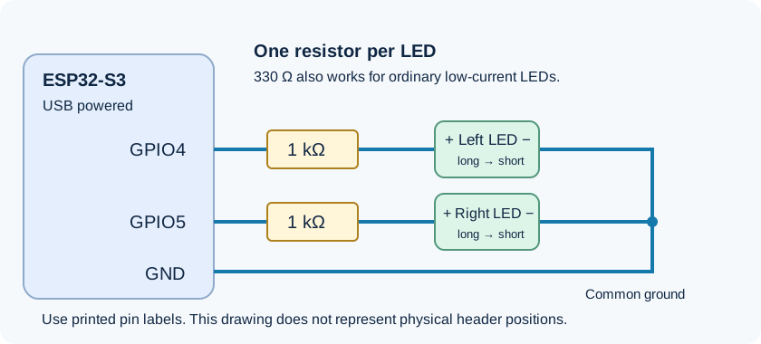
| Board label | Connect to |
|---|---|
4 / IO4 / GPIO4 | 1 kΩ resistor → left LED positive leg (+) |
5 / IO5 / GPIO5 | Separate 1 kΩ resistor → right LED positive leg (+) |
G / GND | Both LED negative legs (−) |
Your two 1 kΩ resistors are suitable for a dim first test; 330 Ω per LED is another option. Do not reuse resistors that are still part of a connected ultrasonic sensor divider.
A longer uncut leg is usually positive. The shorter leg or flat edge is usually negative. Resistors have no direction. Follow the printed GPIO numbers, not the fourth or fifth pin position.
WAGO: one 3-port connector joins board GND and both LED negative legs. Keep each resistor in its own signal branch. The ports in an ordinary WAGO connector are electrically joined: putting both ends of a resistor in the same connector bypasses the resistor.
Power this board by USB. For wired webpage control, use its native USB / OTG connector, not the UART / COM connector. The exact left/right connector placement on the photographed third-party board is unconfirmed; check its printed labels.
02 / Birds — Arduino Nano ESP32
Use the physical board labels D9 and D10. This firmware does not drive lights on the Nano.
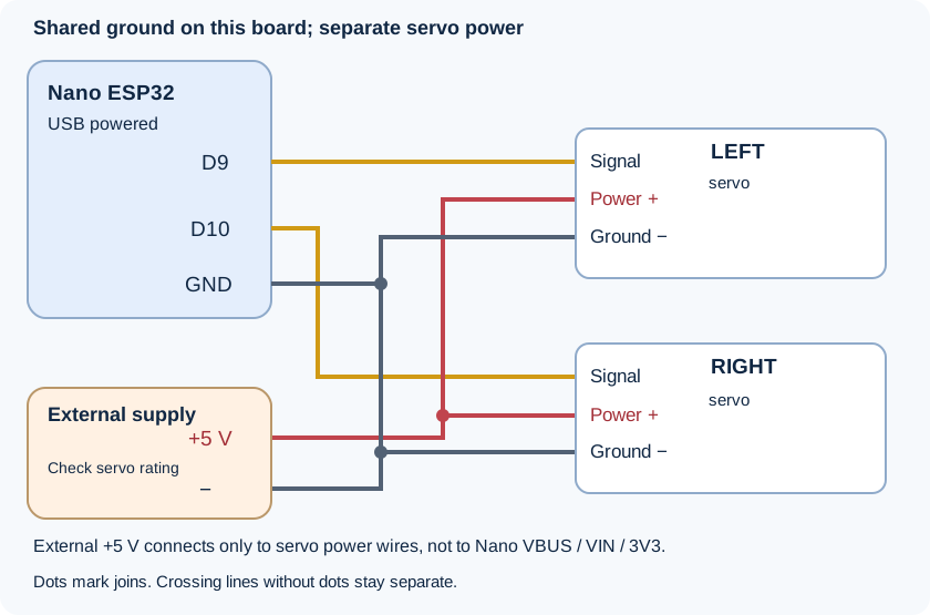
| Wire | Connect to |
|---|---|
| Left servo signal | Nano D9 |
| Right servo signal | Nano D10 |
| Both servo power wires | External regulated +5 V, if supported by the servo rating |
| Both servo ground wires | External supply negative (−) |
Nano GND | The same external supply negative (−) |
Typical servo colours: red = power; brown/black = ground; orange/yellow/white = signal. Verify your servo's markings. Choose supply current capacity from the specifications of both servos; their exact model is not yet confirmed.
- 3-port WAGO: external +5 V, left servo power, right servo power.
- 5-port WAGO: external negative, left servo ground, right servo ground, Nano GND; one port remains spare.
Power the Nano separately through USB. Do not connect external servo +5 V to Nano VBUS, VIN or 3V3 in this setup. Only the ground is shared. Do not power a servo from 3V3 or a signal pin.
Nano GND can be found between D2 and RST, or between B1 and VIN. Both are connected internally. Nano D9 is chip GPIO18; D10 is GPIO21.
First calibrate on a table with bird heads removed or servos unloaded. The first movement click enables the selected servo and moves to its configured rest position. Stop ends servo pulses; it does not disconnect servo power.
03 / Connect and test
- Upload the matching V2.7 sketch to each board after setting its own six-digit control code. Boards remain off at startup.
- Open the controls. Select Birds or Lights, choose Bluetooth or USB, enter that board's code and connect. Bluetooth names are
BirdTap Birds V2andBirdTap Lights V2. - Lights: confirm the resistor setup, select Steady or Blink, then choose Left, Right or Both.
- Birds: connect, then click D9, D10 or Both. The page applies travel settings and enables the selected servo automatically. Start with one small peck.
- Each Stop affects its own board. Stop all affects both. Keep the webpage visible; loss of communication stops outputs after about three seconds.
Each board accepts only one controlling connection at a time. Disconnect Bluetooth before connecting the same board over USB. Close Arduino Serial Monitor before opening USB in the webpage.
iPhone: open an HTTPS deployment of the page in Bluefy and use Bluetooth. The computer's localhost address is not a phone URL. No public HTTPS deployment or iPhone hardware test has been completed yet.
Computer: use a browser with Web Bluetooth or Web Serial, such as supported desktop Chrome/Edge versions. The present USB route does not work in iPhone Safari.
Source code and software checks are not proof of wiring, actual LED brightness or loaded servo performance. This page controls cues manually; it does not detect approaching vehicles.